Introduction
Saving energy through better building operation starts with finding opportunities in five areas that have been shown to have the most frequent problems and the potential for the greatest benefits. Most O&M-related energy waste falls into these major categories:
- Envelope Integrity – Envelope leakage allows for uncontrolled energy losses.
- Equipment Scheduling – Equipment runs when it is not needed.
- Sensor Error – Erroneous sensor data causes increased heating, cooling, or equipment operation, which can affect occupant comfort.
- Simultaneous Heating and Cooling – The same air gets heated and cooled, or hot and cold air streams get mixed together to make warm air.
- Outside-Air Usage – Economizer does not functioning optimally, or excessive outside air causes increased heating and/or mechanical cooling, and sometimes too little air compromises indoor air quality.
Four Key Practices
Developing a Building System Operations Map
Uncovering problems requires a thorough understanding of how a building is used, operated, and maintained. One way to obtain that understanding is to develop a Building System Operations Map.
A Building Systems Operations Map documents the current conditions, focusing on the envelope, scheduling, and on targeting HVAC systems and equipment where common opportunities are found in similar buildings and systems. The map clearly identifies areas for immediate improvement (e.g., changing thermostat setpoints or equipment schedules) and provides the basis for additional evaluation. When completed, the map should document the current uses in the building and how well the operation of the energy systems matches the actual use.
The map should identify major energy-using systems and occupancy types by area. Developing the map requires reviewing the building envelope, utility bills, as-built drawings, and sequences of operations; interviewing building operations and maintenance staff; and cursorily reviewing systems and equipment with a focus on targeting particular HVAC systems and equipment for potential energy savings.
Outline of a typical Building System Operations Map:
For building envelopes, identify:
- Perimeter doors with poor seals or no seals, poor closures
- Duct penetrations (supply, exhaust, and relief) with no motorized dampers, or failed dampers
- Pressurization fans in high-rises with backdraft dampers or leaky motorized dampers
- Architectural details that lack proper or failed sealants
For central boilers, chillers, and cooling towers, identify:
- Operating schedules and sequences of operation
- Large pumps and circulation loops served
- Fan systems served (terminal units and air handlers)
- Major energy systems served (e.g., water heating, sterilizers)
- General maintenance practices and equipment condition
For each major fan system, identify:
- The operating schedule and setpoints
- Occupancy schedule of the area(s) supplied, noting any areas with special extended operating hours
- Any capability of terminal units or baseboards to run independently of main fan
- Sequence of operations for terminal units/baseboard
- Sequence of operations for air handler with a focus on control of outside-air damper, mixed-air temperature, and supply-air temperature
- General maintenance practices and equipment condition
For each major occupancy, identify:
- Occupancy schedule
- Lighting schedule and control method
- Equipment schedule and control method
Document on-going problems and what building operators are doing to compensate:
- Undersized equipment
- Oversized equipment
- Spaces that can’t maintain temperature settings
- Building pressurization problems
- Major HVAC equipment with higher failure rate than typical
Using Energy Use Index (EUI) and Benchmarking
A closer look at a building’s past energy performance and energy-use pattern, and comparing it to typical similar buildings energy use can further identify problem areas.
The energy-use index (EUI) is the amount of energy used by a building per square foot of building floor area. By normalizing energy use to floor area, buildings can be benchmarked and compared for relative energy performance. An EUI can be based on whole-building energy use or on specific end uses such as lighting or heating.
A whole-building EUI is a good measure of overall energy-savings potential. Much data is available on whole-building EUI for many building types. A building with a higher EUI than the average similar building is more likely to have energy-saving opportunities and the magnitude of the difference hints at the magnitude of potential savings.
Comparing the building’s past performance to current energy performance can provide further insight and might lead to additional energy savings. Has the EUI increased over time? Can the increase be correlated to a change in hours of occupancy, a decrease in vacant space, equipment additions, equipment changes? If not, it probably indicates an opportunity to reduce energy use.
The Performance Indicators page discusses tools to help you understand your building’s energy use.
Targeting the Envelope
The building envelope is the largest single component of any HVAC system. It has to be able to contain the air being conditioned by the HVAC system in order for the HVAC system to operate at its highest potential efficiency.
Targeting HVAC Systems and Equipment
Any HVAC system can be targeted to improve scheduling, outside-air use, and sensor calibration. The design of the following HVAC system types make them prone to excessive energy use in certain situations.
| System and Equipment Type | Where Found | Opportunities for Savings |
|---|---|---|
| VAV with Reheat | Hospitals, offices, other | Reheat/recool, zone scheduling |
| Constant-Volume with Reheat | Hospitals, pre-1980 offices and other | Reheat |
| Dual Duct | Hospitals, pre-1980 offices and other | Simultaneous heating and cooling, zone scheduling |
| Multizone Fan | Hospitals, pre-1980 offices and other | Simultaneous heating and cooling, zone scheduling |
| Central AC with Perimeter Heating | Pre-1980 offices and other | Simultaneous heat and cooling, zone scheduling |
| Heat Recovery | Hospitals and others with high minimum outside air | Dirty coils, coil bypass not optimized, non-operational |
| Boilers | Hospitals and other with central HVAC | Inefficient combustion, poor staging, steam or steam trap leaks |
| Chillers | Hospitals, large office, other with central HVAC | Poor staging, dirty or corroded tubes, increase chilled water temperature |
| Compressed Air System | Hospitals, shops, older buildings | Poor staging, leaks |
| Heat Pumps | Small buildings | Control of auxiliary heat |
| Water-Loop Heat Pumps | Most building types. | Control of loop temperature and outside air, zone scheduling |
The Top Five Savings Opportunities
Envelope Integrity
The cheapest energy is that which you do not use. Allowing conditioned air to escape the envelope in an uncontrolled manner guarantees high energy bills and tenant comfort issues.
Visitors will complain when envelope leakage causes the Lobbies to become excessively negative, bringing cold drafts deep into the building and up the elevators. In extreme cases, the elevator doors can be hard to close against the pressure differential across the doors. Buildings without revolving doors or motorized ADA doors can experience problems with tenants even being able to get into the building!
Leaky exterior doors or roof hatches at the roof produce stack effect in the stairwells, which can prevent doors on lowers floors from completely closing after being used. This allows for leakage from the specific floor, plus creates a security concern.
Elevator machinery rooms that are naturally ventilated with louvers and exhaust fans are prime locations for losing air. Typically the worst case is at night when there is no one around to observe how the dampers are reacting to differential temperatures. Stack effect can easily lift backdraft dampers. Adding motorized dampers, or even better, adding mechanical refrigeration can allow the space to be sealed hermetically, preventing air losses. If the facility has water-source heatpumps, adding a unit will allow the rejected heat from the machinery to be brought back into the building HVAC system for heating in other parts of the building.
Life safety pressurization fans are also a source of problems for several reasons. Low leakage motorized dampers should be installed at every unit, regardless of location in the building. A time delay needs to be programmed, or control can be through a end-limit switch in the damper actuator, which prevents the fan from starting before the damper is wide open. Dampers should be checked quarterly to ensure they stayed closed , and there are no failed operators or slipped linkages. Life safety dampers are designed to fail open.
For buildings with associated garages, look for air transfer between the garage and building. Sometimes the garage exhaust fan system can actually pull conditioned air from the building. Make sure vestibules and doors are tightly fitting with full seals. Conversely, a building under negative pressure in the main lobby due to stack effect can pull garage air into the building, bringing carbon monoxide and carbon particulates along.
Every CFM you prevent from escaping the building in an uncontrolled manner reduces the amount of air you need to condition, regardless of whether is came in through the front door or through the air handlers.
Equipment Scheduling
The easiest way to save equipment energy is to shut it off.
Occupants rarely complain when equipment runs longer than needed, so it’s easy for this problem to go unnoticed. A plan or procedure should be put in place to check occupant requirements and re-evaluate equipment operating schedules regularly. Typically this should be performed twice a year and whenever there is a major tenant change.
Poor equipment scheduling has many negative impacts:
- Energy use increases proportionally to operating hours for most non-modulating equipment such as lighting, plug loads, and constant-volume fans.
- Fan systems with ventilation or exhaust usually use more energy at night because the ventilation or make-up air is colder.
- Staging equipment to reduce demand charges can actually increase energy costs. For example, some facilities may stage in equipment over an hour or two to avoid demand spikes. The spike in current required to start motors does not last long enough to affect billing demand (which is usually measured over 15- or 30-minute intervals). The equipment comes online earlier than necessary, increasing consumption while having no effect on the demand charge.
- Longer operating hours result in shorter equipment life and more frequent replacement of lamps, ballasts, filters, belts, electric heating coils, contactors, relays, motors, pumps, chillers, boilers, compressors, and other equipment.
- Increased operating hours cause chiller bundles, boiler tubes, fan coils, evaporator coils, and condenser coils to require cleaning more frequently.
Walking through the building when it is unoccupied is a good first step in identifying unnecessary equipment operation. If equipment is running, look for a reason. It is usually obvious that a lamp or printer should be off, but HVAC equipment may be running to supply a computer room that needs continuous conditioning, or to condition some other process load.
Systems that often experience scheduling problems include:
- Lighting
- Plug and Process Loads
- Fan Systems
- Chillers and Boiler Availability
- Pumps
Lighting
Manually controlled (wall switch) lights are usually turned on by occupants as they arrive, but not always turned off as they leave. Occupants may not hesitate to turn off lights in a small room, but are reluctant to turn off large banks of lights if they think someone else might still be in the space.
Things to look for include:
- Is a specific person responsible for turning off the lights?
- Does the custodial staff turn off lights after hours as they go through the building?
- Do the light switches have “turn off” labels?
If lighting is controlled by a time clock:
- Does the programming match the occupant schedule?
- Does the schedule account for holidays and weekends?
- Is someone responsible for checking the programming regularly to make sure it meets current occupancy requirements?
- Do the lights actually turn off as programmed?
- Have temporary, special-event schedules been reprogrammed back to normal schedules?
If there are motion sensors:
- Are they properly oriented to sense occupants?
- Has the time interval to switch the lights off after occupancy been properly set?
If there are daylight controls:
- Are the sensors situated properly?
- Are the appropriate light levels set?
If problems are suspected, you can attach a data logger to the lighting circuit and take readings at 15-minute intervals to identify the extent of the problem.
Plug and Process Loads
Plug and process loads are generally manually controlled by occupants. Like manually controlled lighting, these loads are normally turned on by occupants, but are often left on longer than necessary. Unlike lighting, custodial staff are not usually empowered to turn off plug loads like computers or medical equipment as they go through a building each evening. Some equipment such as servers, fax machines, and medical equipment may need to run continuously.
Typical scheduling problems to look for include:
- Does the tenant or IT department have a policy or system in place to make sure computers that have an Energy Star power-saving mode have it enabled?
- Does the tenant have a policy to encourage employees to turn off there equipment when leaving?
- Are monitors turned off when not in use?
- Are printers and scanners turned off when not in use?
Fan Systems
Most fan systems are controlled by an energy-management system or time clock. Typical scheduling problems to look for include:
- Do the programmed schedules match occupancy requirements?
- Do programmed schedules accommodate holidays and weekends?
- Are systems checked to make sure fans actually turn off when programming indicates they are off?
- Are the fans running after hours for minimal tenant occupancy?
- Is optimum start and stop utilized?
- If optimum start/stop is not available, are start times adjusted seasonally by the building operator?
- Can fan-powered VAV boxes operate independently of the air handler and, if so, are they programmed to match occupancy?
- Are exhaust fans interlocked with the air handler or controlled separately?
- Can baseboards operate independently from the fan system and, if so, are they programmed to match occupancy?
Chiller and Boiler Availability
Typical scheduling issues with chillers and boilers include:
- Are chillers locked out when the outside-air temperature is low?
- Are boilers locked out when the outside-air temperature is high?
- Are chillers and boilers prevented from operating at the same time?
- Are there controls to shut off the boiler or chiller when there is no load?
Pumps
Typical scheduling issues for pumps include:
- Are DHW circulating pumps scheduled off when the building is unoccupied?
- Are HW pumps scheduled off when the building is unoccupied and the boiler is off?
- Are CW pumps scheduled off when the building is unoccupied and the chiller is off?
- Are condenser pumps scheduled off when the building is unoccupied and the chiller is off?
- Are HW pumps controlled to run only when there is a demand for HW or when the outside air is cool?
- Are CW pumps controlled to run only when there is a demand for CW or when the outside air is warm?
- Are condenser pumps interlocked to run only when there is a coil or process demand for CW?
Sensor Error
Sensor error can increase energy use, compromise occupant comfort, and prevent plant and system loads from being met. This is most often caused by uncalibrated sensors, but can also be due to incorrectly placed sensors, failed sensors, or mistakes in control set-up.
While building systems use many sensors, critical control sensors are the most likely to cause severe energy penalties. For example, while space-temperature sensors cause energy waste and comfort problems, the effect on energy is usually minor and restricted to one zone. On the other hand, errors of a critical control sensor such as the temperature of return air at the air handler can cause large energy penalties affecting many zones, yet may not cause comfort issues. Sensor error is hard to detect unless the sensors are calibrated regularly.
A wide variety of sensor types are available for HVAC use. Many can be calibrated and others need to be replaced periodically. It’s important to know the specifications of the specific sensor in order to maintain it. Older CO2 sensors need to be calibrated as often as every 2 months, and some newer sensors are guaranteed to be accurate for the service life of the sensor-5 to 15 years.
Control sensors with the most potential to have a significant effect on energy use are generally those used to implement resets and control outside air at air handlers and central plants. While the impacts can be huge, the fix is simple-regular calibration.
Critical control sensors include:
- Mixed-air temperature sensor
- Return-air temperature sensor
- Outside-air temperature sensor
- Supply-air temperature sensor
- Chilled-water temperature sensor
- Hot-water temperature sensor
- Carbon dioxide sensor
- Carbon monoxide sensor
Some questions to ask:
- Are sensors calibrated at least annually?
- Are critical control sensors calibrated at least twice a year?
- Are critical control sensors replaced on a regular schedule as they approach the end of their service lives?
Sensor Issues in Disguise
Many sensor problems can appear to be other issues, for example:
- Plant and system loads not met
- Reset schedule not working
- Outside-air economizer not functioning properly
- Boilers and chillers on when not needed
- Equipment not modulating as expected
- Simultaneous heating and cooling
Simultaneous Heating and Cooling
Most central HVAC fan systems use some form of reheat. Central fan systems are designed to supply space conditioning to multiple areas in a building. Each area has its own space-conditioning needs. Typically a central fan supplies cool air to one or more zones. At the zone level, the quantity of air is usually modulated to satisfy the cooling load or may need to be reheated to meet a call for heating. A typical office floor will have electric or hydronic coils installed in the duct work or in the fan boxes serving the perimeter areas, while the central area is only cooled.
The temperature of the cool air leaving the air handler (primary supply-air temperature) determines the amount of reheat required in the various zones. Control strategies optimize the supply-air temperature and reduce reheat. Usually the supply air is reset to the highest temperature that can still meet the largest cooling load. If the control strategy is not optimized, the supply air will be cooler than necessary and reheating it will use more energy than necessary.
For example, if the primary air temperature were off by just 1 degree from optimum, it would cost approximately $1,000/yr in electric reheat (at 6 cents/kWh) on a system with 20,000 cfm of primary air operating 10 hours/day, 5 days/week.
See the symptom page on “Mixed-air temperature is near outside-air temperature during cooling mode ” for more information about diagnosing simultaneous heating and cooling.
See the Case Study of a Sensor Calibration Problem for an example of simultaneous heating and cooling.
There are many variations of central HVAC fan systems that have similar problems of simultaneous heating and cooling.
The following are systems that should be targeted in detail for energy saving O&M opportunities:
- VAV with Reheat
- Constant-Volume with Reheat
- Dual Duct
- Multizone Fan
- Central AC with Perimeter Heating
In addition to energy costs, simultaneous heating and cooling increases operational costs. When the central system delivers cooler air than required, the zone reheat coils must temper the air before it is delivered to the space. The heating and cooling systems work against each other. This creates additional wear on electric heating coils, contactors, hot-water pumps, chilled-water pumps, boilers, chillers, and auxiliaries.
Chillers and boilers may run when none are needed, or a larger chiller or boiler may be sequenced on when a smaller one could have met the load. Electric reheat coils are turned on when they could have been left off. Variable-flow chilled-water and hot-water systems operate at higher flow rates than necessary. Equipment capacity is reduced because the heating and cooling systems are working against each other. This can lead to underheated or undercooled areas and occupant discomfort when capacity is exceeded. Maintenance costs and equipment reliability are both affected.
Outside-Air Usage
Outside air is supplied to a building by the ventilation system in order to displace indoor air pollutants and provide adequate ventilation for the building occupants. Proper ventilation rates are needed to maintain indoor air quality. Building codes require a minimum ventilation rate, usually based on ASHRAE Standard 62. While buildings are only required to meet the ventilation code in effect at the time of construction or major remodel, it’s good practice to provide ventilation that matches the latest codes and standards-if your HVAC system is capable.
Examples of the currents requirements of Northwest states are:
- Idaho – International Building Code.
- Oregon – Chapter 4 of Oregon Mechanical Specialty Code. Based on ASHRAE Standard 62 with additional requirements for Demand Controlled Ventilation.
- Montana – ASHRAE 90.1 for commercial spaces.
- Washington – Default ventilation rates based on ASHRAE Standard 62-1989 with alternate design allowed based on ASHRAE Standard 62.1-2004
Economizers
Many buildings use an outdoor air economizer which uses outside air for “free” cooling when its temperature is below the return air temperature. The economizer varies the outside-air quantity from the minimum ventilation rate up to 100% outside air as needed to cool the building.
Scheduling
Energy codes generally require that outside-air dampers are closed when the building is unoccupied, and open to the minimum ventilation rate when it is occupied and being heated. When the building needs cooling the economizer activates and allows additional outside air.
Demand-Controlled Ventilation
Demand-controlled ventilation adjusts the amount of outside air based on the number of occupants in the space. It is best applied to areas with large variations in occupancy such as auditoriums, gymnasiums, and large conference rooms. By adjusting the ventilation rate to meet actual rather than peak occupancy requirements, you save energy and maintain indoor air quality.
CO2 is an easily measured by-product of humans. Demand-controlled ventilation typically uses CO2 sensors to control the minimum ventilation rate based on the difference between ambient outdoor-air CO2 levels and indoor space CO2 levels. The latest ASHRAE standard 62.1-2004 does not specify a specific CO2 difference that must be maintained but older versions of the standard recommended 700 ppm as an adequate differential for controlling odor.
Fixed-Air Systems
In some cases, the fan system is designed to provide outside air at a fixed rate any time the fan runs. This is used either in very small systems or in special cases that require 100% ventilation for hazardous processes. Many current codes require heat recovery on systems that use 70% or more outside air.
Energy Impacts
Heating outdoor air is an energy-intensive and expensive process. Heating 20 cfm (typical for 1 person) of outside air for 14 hours/day, 5 days/week using electric resistance heat at 6 cents/kWh costs about $28/yr in a typical Seattle year. If an air handler supplies an extra 1,000 cfm of outside air it costs approximately $1400/yr under these conditions.
Ideally, a building’s ventilation system will provide only the minimum outside air to meet occupant air-quality needs, except when it can be used for cooling. Ventilation systems can experience many problems.
Some typical problems include:
- Minimum ventilation rate is never adjusted for a change in occupancy.
- Minimum ventilation rate is set wrong by damper position rather than a measured airflow.
- Damper leaks when in the unoccupied position.
- Damper does not close when in unoccupied mode.
- Damper stuck in one position.
- Temperature sensors used by economizer are out of calibration or have failed.
- CO2 sensor is improperly located
HVAC Systems and Major Equipment
VAV with Reheat
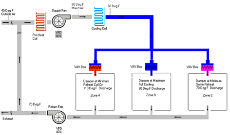
The figure below shows a simplified schematic of a typical VAV system with zone reheat and sample operating points. The central fan supplies cool air to the VAV boxes and the VAV boxes modulate flow as needed to cool the space. When heating is needed, the VAV boxes reduce flow to minimum and use the reheat coil to control discharge temperature. There are several variations of this system (parallel and series fan-powered VAV boxes) but they all use the same basic reheat strategy illustrated in this example.

VAV with Reheat
In this example the economizer is modulating to produce 60°F mixed air, matching the setpoint temperature of the primary supply air. No cooling is needed from the cooling coil. The three VAV boxes use the 60°F supply air to meet the zones HVAC demands.
Zone A needs heating so the VAV box reduces flow to minimum and turns on the heating coil to increase the discharge temperature from 60°F to 110°F.
Zone B needs full cooling so the VAV box provides full flow at 60°F.
Zone C needs no cooling or heating so it reduces flow to minimum and uses reheat to increase the temperature of discharge air from 60°F to 70°F providing neutral air to the space.
This example illustrates that the temperature of the cool air leaving the air handler (primary supply air temperature) determines how much reheat is required both in heating zones and in neutral zones. Control strategies are used to optimize the supply-air temperature and reduce reheat. The supply-air temperature can be reset based on time of year, time of day, outside-air temperature, return-air temperature, the temperature in a representative space, the temperature in a worst-case cooling zone, or some combination of these. If existing controls do not automatically reset supply-air temperature, it should be manually reset at least seasonally.
The temperature of primary supply air is commonly set to about 55°F for cooling design with central-fan systems. Resets can typically increase primary-supply-air temperature to 60°F during cold weather and, with very good design, up to 65°F (though this is not common).
In this example, if the primary-supply-air temperature were fixed at 55°F (instead of reset to 60°F) the heating energy for Zone A would increase by 10% and for Zone C by 50%.
Primary targets of a VAV tune-up should be the control strategy for primary-supply-air temperature and the related sensors and dampers. The following items all have a major impact on the temperature of primary supply air and related energy use:
- Calibration of the temperature sensor for primary air
- Calibration of the temperature sensor for mixed air
- Calibration of the temperature sensor for return air
- Calibration of the temperature sensor for outside air
- Economizer dampers
- Calibration of the temperature sensor for space temperature (when used to reset primary-supply-air temperature)
Constant-Volume with Reheat
The figure below is a simplified schematic of a constant-volume system with zone reheat and sample operating points. The central fan supplies cool air to the reheat boxes and the reheat coil is used to control discharge temperature. Constant-volume fan systems with reheat are generally no longer allowed in new construction because of their high energy use. The VAV-with-reheat system shown above is similar except that it reduces air volume as the cooling load decreases instead of activating a reheat coil. Constant-volume-reheat fan systems are generally excellent candidates for retrofitting to VAV. When VAV retrofits are not practical for budgetary or other reasons, it is extremely important that the constant-volume-reheat fan system be tuned for the best energy performance possible.

Constant-Volume with Reheat
In this example the economizer is modulating to produce 60°F mixed air, matching the setpoint temperature of the primary supply air. No cooling is needed from the cooling coil. The three reheat boxes use the 60°F supply air to meet the zones’ HVAC demands.
Zone A needs heating so the reheat coil increases the discharge temperature from 60°F to 90°F.
Zone B needs full cooling so the reheat coil is off and the discharge temperature is 60°F.
Zone C needs no cooling or heating so the reheat coil increases the discharge temperature from 60°F to 70°F providing neutral air to the space.
This example illustrates that the temperature of the cool air leaving the air handler (primary-supply-air temperature) determines how much reheat is required both in heating zones and in any zone that needs less than full cooling. Control strategies are used to optimize the supply-air temperature and reduce reheat. The supply-air temperature can be reset based on time of year, time of day, outside-air temperature, return-air temperature, the temperature in a representative space, the temperature in a worst-case cooling zone, or some combination of these. If existing controls do not automatically reset supply-air temperature, it should be manually reset at least seasonally.
The temperature of primary supply air is commonly set to about 55°F for cooling design with central fan systems. Resets can typically increase primary-supply-air-temperature to 60°F during cold weather and, with very good design, up to 65°F (though this is not common).
In this example, if the primary-supply-air temperature were fixed at 55°F (instead of reset to 60°F) the heating energy for Zone A would increase by 17% and for Zone C by 50%.
Primary targets of a tune-up of a constant-volume-reheat system should be the control strategy for primary-supply-air temperature and related sensors and dampers. The following items all have a major impact on the temperature of primary supply air and related energy use:
- Calibration of the temperature sensor for primary air
- Calibration of the temperature sensor for mixed air
- Calibration of the temperature sensor for return air
- Calibration of the temperature sensor for outside air
- Economizer dampers
- Calibration of the temperature sensor for space temperature (when used to reset primary-supply-air temperature)
Dual Duct
The figure below is a simplified schematic of a dual-duct system. The central fan supplies air to the hot deck and cold deck. Mixing boxes mix air from the hot duct and cool duct as needed to maintain space temperature. There are many variations of this system (variable-air-volume mixing boxes, dual supply fans, hot deck with 100% return air), but they all produce simultaneous heating and cooling.
Dual Duct
In this example, the economizer is modulating to produce 60°F mixed air, matching the setpoint temperature of the cold deck. No cooling is needed from the cooling coil. The hot-deck heating coil is “on” raising hot-deck temperature from 60°F to 85°F. The three mixing boxes mix various quantities of 60°F and 85°F air to achieve a discharge temperature that meets the zones’ HVAC demands.
Zone A needs full heating so the mixing box shuts off the cold-duct damper and opens the hot-duct damper 100% to produce discharge air at 85°F.
Zone B needs full cooling so the mixing box shuts off the hot-duct damper and opens the cold-duct damper 100% to produce discharge air at 60°F
Zone C needs no cooling or heating so it mixes 60°F and 85°F air to produce discharge air at 70°F.
This example illustrates that simultaneous heating and cooling is inherent in the design of a dual-duct system. If Zone A or Zone B had needed less than full heating or cooling, the system would have mixed air from the other ducts as it did for Zone C. To minimize simultaneous heating and cooling, hot-deck temperatures should be reset cooler as heating load decreases and cold-deck temperatures should be reset warmer as cooling load decreases.
Control strategies are used to optimize the hot-deck and cold-deck temperatures. Temperatures can be reset based on time of year, time of day, outside-air temperature, return-air temperature, the temperature of a representative space, the temperature in a worst-case cooling/heating zone, or some combination of these. If existing controls do not automatically reset hot- and cold-deck temperatures, they should be manually reset at least seasonally.
The design cold-deck temperature is commonly set to about 55°F and the design hot-deck temperature is commonly set between 105°F and 130°F. Resets can typically increase the cold-deck temperature to 60°F during cold weather and, with very good design, up to 65°F (though this is not common). Resets can typically decrease the hot-deck temperature to 70°F (or straight return air) during hot weather.
In this example if the cold-deck temperature were fixed at 55°F (instead of reset to 60°F) and the hot-deck temperature fixed at 120°F (instead of reset to 85°F), Zone A would be mixing 120°F air with 55°F air to make 85°F air, Zone B would be mixing 120°F air with 55°F air to make 60°F air, and Zone C would be mixing 120°F air with 55°F air to make 70°F air. Heating for Zone A and Zone B increases by 20% and 50% respectively, and Zone B goes from no heating to needing a mix of 120°F air and 55°F air to make 60°F air. Depending on relative flows to each zone, the overall energy use of the heating coil could increase from a minimum of 30% up to over 100%.
Primary targets of a dual-duct tune-up should be the control strategy for hot- and cold-deck temperatures and related sensors and dampers. The following items all have a major impact on the temperature of the hot and cold decks and related energy use:
- Calibration of the temperature sensor for cold deck air
- Calibration of the temperature sensor for hot deck air
- Calibration of the temperature sensor for mixed air
- Calibration of the temperature sensor for return air
- Calibration of the temperature sensor for outside air
- Economizer dampers
- Mixing-box dampers (leakage)
- Calibration of the temperature sensor for space temperature (when used to reset the hot- or cold-deck temperature)
Leakage of the mixing-box damper is critical with this system. If a mixing box leaks from the heating duct when it should be fully closed, it will increase the box discharge temperature and require a colder cold-deck temperature to achieve the required discharge temperature. The converse is true for leaking cold-duct dampers. The leakage causes both suboptimal deck temperature and simultaneous heating and cooling for the leaking box.
Multizone Fan
The figure below is a simplified schematic of a multizone fan system. It is the same design as the dual-duct system except the location of the mixing dampers is at the air handler instead of at mixing boxes in the various zones. See the section on Dual Duct systems for a description of operations and issues applicable to both systems.
Multizone Fan
Central AC with Perimeter Heating
The figure below is a simplified schematic of central air conditioning with perimeter heating and sample operating points. The central AC in this example is a VAV system with no reheat, and the perimeter heating is baseboard. The areas served by the VAV and baseboard are open to each other. The VAV system provides ventilation and cooling while the baseboard offsets heat loss from the building shell when needed. There are many variations of this layout that use different cooling or heating equipment, but they all produce simultaneous heating and cooling along the air border between the perimeter and interior spaces.
Central AC with Perimeter Heating
In this example, the VAV system is producing 60°F supply air and varying it as needed to cool the space and/or provide ventilation. The three zones each have baseboard heat at the perimeter in addition to VAV supply toward the interior.
In Zone A, the baseboard and VAV box use separate space-temperature sensors and have setpoints that should prevent or minimize simultaneous heating and cooling.
In Zone B, the VAV box and baseboard use the same sensor and a DDC system would control the VAV box and baseboard to prevent simultaneous heating and cooling. Hunting between heating and cooling would be prevented if a proper deadband and throttling range are programmed.
In Zone C, the baseboard and VAV box use separate space-temperature sensors and have setpoints that would cause simultaneous heating and cooling. Each thermostat is set to 70°F causing overlap in the throttling range between heating and cooling. Even if the cooling thermostat is set to 72°F and heating thermostat is set to 70°F there is little tolerance for throttling range or sensor calibration error.
Central AC perimeter heating systems should be tuned to prevent or minimize simultaneous heating and cooling. Things to look for include:
- Regular calibration of space-temperature sensors and thermostats
- Heating and cooling setpoints at least 4 degrees apart
- Deadbands and throttling ranges that prevent hunting between cooling and heating
- Locks or protective covers that prevent occupants from changing thermostat settings