Introduction
Note: This symptom is limited to single-duct systems that have both heating and cooling coils located in the air handling unit (AHU). Dual-duct and multizone systems are specifically designed for simultaneous operation of both coils.
With no cooling or heating (valve position for both is closed, or % = 0), supply-air temperature (SAT) should equal the mixed-air temperature (MAT) plus a few degrees for fan heat (usually two degrees in most commercial systems, and up to four degrees in high-pressure systems). If the temperature difference is greater than what can be attributed to fan heat, then there may be a problem with the heating coil.
Preheat and heating coils are typically located between the outside-air (OSA) intake and the cooling coil to protect the cooling coil from freezing conditions. This applies to both draw-through and blow-through configurations. If humidity control is available, then the primary (or a supplemental) heating coil may be downstream of the cooling coil. The heating coil can be electric, hydronic (heating water), or steam, and different causes of this symptom will apply to each type.
How This Wastes Energy
With both coils operating, the downstream cooling coil must remove some, if not all, of the heat added by the heating coil to maintain the SAT setpoint.
Possible Causes of Symptom
The list below shows some of the possible causes of this symptom. The cause of a symptom can be an energy-performance problem that can be fixed, or it may be explained by an unavoidable aspect of your current system that would probably require a capital project to change. Follow the steps described after the table to determine the possible cause of this symptom. If you find a problem, perform the suggested trend logging to confirm that the problem exists and, later, that you have solved the problem.
Inspection Steps:
- Explanation: The system is controlling humidity.
- Explanation: Chilled-water pump could be running, possibly due to freezing conditions.
- Problem: Temperature setpoints are overridden.
- Problem: Valve actuators can't overcome the differential water pressure to fully shut off the system.
- Problem: Valves are manually adjusted.
- Problem: Coil control valve has failed, is stuck in the open position, or is allowing fluid to leak by.
How to Find the Problem(s) by Inspection
As noted above, for this condition to occur, both the cooling and heating systems must be active.
Inspection Step 1
Review the design criteria for the system to see if humidity control is part of the design. Under some conditions, the cooling coil will be active to reduce moisture in the air stream. It typically cools the air below the dry-bulb-temperature setpoint, so the air stream must be reheated to reach the SAT setpoint. In such cases, the heating coil is located downstream of the cooling coil. If this applies in your case and conditions call for dehumidification, then having both coils active is permissible. However, if multiple AHUs supply the same area, make sure they are operating from a single set of sensors and not independently. All AHUs should be operating in the same mode at the same time. Otherwise, they can work against each other- one is heating while the other is cooling.
Inspection Step 2
Review the design criteria and the DDC-system programming to see if the chilled-water-system pump is online for freeze protection. It is relatively common to circulate chilled water through the coil to prevent freezing, especially in climates where freezing is rare (in which case, protecting the equipment is considered more important than conserving energy). Alternatives to this practice are:
- Draining the cooling coils in the winter. This is standard practice in two-pipe distribution systems.
- Having solenoid dump valves that automatically drain the cooling coil if a potential freezing condition exists. (Make sure your water additives meet your local waste codes.)
If this is condition applies, the total impact on energy usage is the sum of the chilled-water pump energy and the energy that the cooling coil removes from the air stream.
Inspection Step 3
Inspect the DDC system to verify that the SAT setpoint has a reset schedule and has not been overridden. Verify the original setpoint as commissioned or as specified in the operating plan. If the setpoints have been overridden, find out why before correcting the problem. Sometimes software interlocks are not programmed to prohibit simultaneous heating and cooling, and the coils may be controlling to different setpoints. Heating may be active to try to reach a certain temperature based on a reset schedule using OSA, while cooling is active to try to maintain a terminal-unit damper at a certain position.
Inspection Step 4
Inspect the DDC commands to the heating- and cooling-coil valves. Only one should be active. If there are no end switches providing feedback about valve position to the DDC system, you will need to inspect the valves. Valve actuators for 2-way and 3-way valves have different torque requirements. Actuators on 2-way valves need more torque to overcome the pump static head pressure. Three-way valves just divert the flow, not overcome it, so their actuators need much less torque. A 3-way valve may have been converted to a 2-way but the actuator was not replaced. Inspect the valves to make sure their position is as indicated by the DDC system.
Inspection Step 5
Some motorized and pneumatic control valves can also be adjusted manually. Make sure the valves can freely travel their entire stroke as commanded by the DDC system and that there are no manual adjustments that limit their stroke. If it is a hybrid control system-that is DDC sensors with pneumatic controllers-verify that the electro-pneumatic (EP) controller is working properly and allowing full control air to the pneumatic diaphragm. If the control valve is wide open, make sure the isolation valves to the coil are not being used for flow control.
Inspection Step 6
If a valve can't make the full stroke or doesn't respond to a DDC command, remove and inspect the actuator for proper operation. The valve should also be removed and dismantled for inspection and repair. Look for problems with the seating surfaces, both on the valve disc and body. Inspect the strainer upstream of the control valve and make sure it is clean and that a screen is installed. (A good indicator of a leaking valve is a differential temperature between the inlet and outlet piping that you can identify using a thermometer or your hands. Just make sure you don't get burned while checking for this.)
How to Confirm the Problem(s) by Trend Logging
Trend log the following:
- Outside-air temperature (OSAT)
- Supply-air temperature (SAT)
- Mixed-air temperature (MAT)
- Return-air temperature (RAT)
- Cooling valve (%)
- Heating valve (%)
- Heating-coil leaving-air temperature (LAT)
Trending the heating-coil LAT will most likely require portable temperature loggers. Graph the temperatures and see how the coil LATs vary with respect to the valve positions, or percent of capacity.
Example of Normal Operation
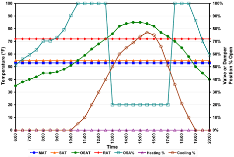
In this example, the system is economizing so the MAT is 2F below the SAT setpoint because of fan heat. The AHU is modeled as constant volume to simplify the graphs.
The graph below shows normal cooling operation. The cooling-coil control valve is at 0% when the OSAT is 2 degrees below the SAT. The heating valve is closed throughout the day. If your graph looks like this, the problem should be solved.
Normal operation
Example of Abnormal Operation
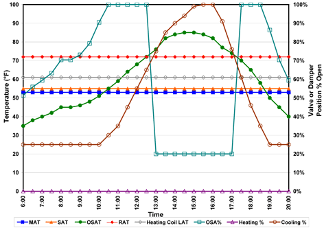
The graph below is similar to the one above, except that the baseline for the cooling-coil control valve appears to be 25%. If your graph looks like this, a leaky valve at the heating coil is causing heat gains. The heating-coil LAT was trended, showing a constant pickup of about 8 degrees. Re-inspect the system starting from Inspection Step 4.
Abnormal operation: leaking heating valve
Labor Skills Required to Find and Resolve the Problem
- DDC system operator/programmer
- Service mechanic